How machine vision systems detect defects in composite airframes
Lead Author
Published
Views:
Composite airframes offer weight and performance advantages, but their layered construction makes inspection a demanding task. A faint wrinkle in a newly laid ply may indicate a manufacturing problem, while a barely visible surface mark on an aircraft in service may warrant a closer assessment. For quality control and safety teams, the challenge is not simply finding an unusual feature; it is deciding what that feature means, documenting it, and routing it to the right inspection or disposition process.
Machine vision systems support those decisions by combining cameras, controlled illumination, positioning equipment, and image analysis. They can make surface inspection more repeatable and provide records for review. They do not, however, see every defect in a composite laminate. Understanding that distinction is essential when building an inspection process that supports airworthiness rather than creating a false sense of certainty.
What machine vision can see on a composite airframe
A vision system detects differences in the light returned from a surface and interprets those differences against defined inspection criteria. Depending on the setup, an image may reveal changes in texture, shape, color, or reflectivity. The system then identifies features that could correspond to a defect, measures them where possible, and presents the result for acceptance or review.
Typical targets include:
- Fiber misalignment and wrinkles: Visible deviations in fiber direction or surface contour, particularly during layup when material is still accessible.
- Gaps, overlaps, and misplaced material: Irregularities between adjacent tapes or plies that may be observable before later layers conceal them.
- Surface cracks and scratches: Linear indications on accessible surfaces, subject to image resolution, lighting, and surface condition.
- Impact-related indications: Dents, coating damage, or other visible marks that can prompt further investigation.
- Foreign material and surface contamination: Objects or residue that contrast sufficiently with the surrounding material under the chosen imaging conditions.
Detecting an indication is not the same as establishing its structural significance. A visible mark may be cosmetic, or it may be associated with damage extending beneath the surface. Conversely, a laminate can contain subsurface damage without an obvious external sign. The applicable engineering criteria and inspection instructions determine what happens next.
From light to an inspection decision
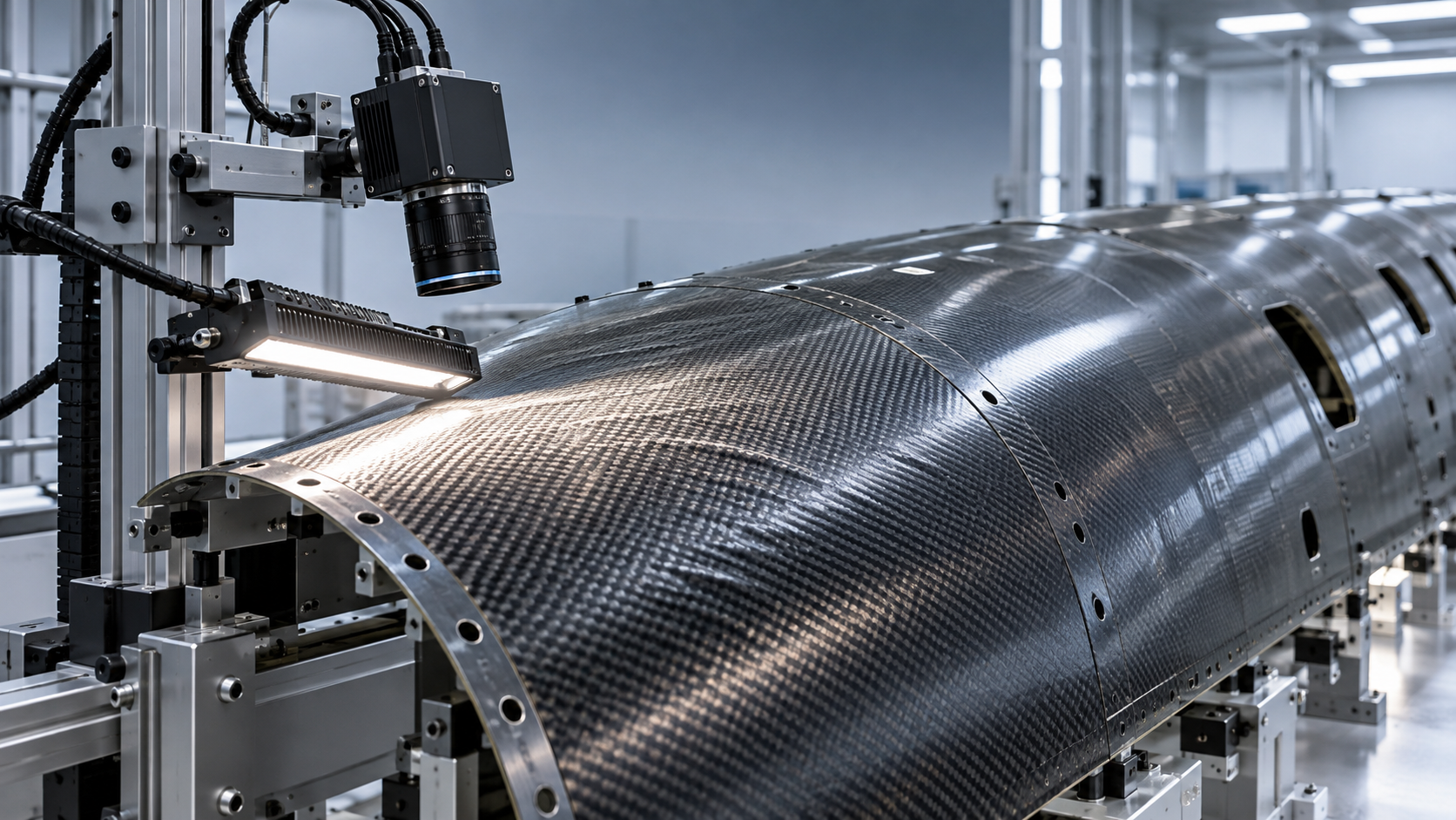
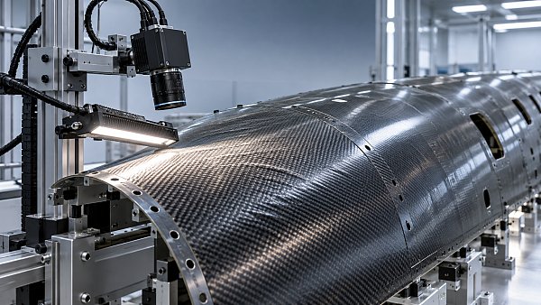
Imagine a production team inspecting a curved composite skin after a layup operation. An operator can scan the area by eye, but fatigue, reflections, and variations in working distance can make subtle features difficult to assess consistently. A machine vision station addresses those variables by controlling how images are captured and analyzed.
1. Capture an image suited to the defect
The camera, lens, and illumination must be selected together. Resolution and field of view need to be sufficient for the smallest indication the process is expected to detect, while focus and working distance must remain suitable across the inspected area. A system covering a large fuselage section in one image may lack the detail needed for a fine surface crack; several overlapping views may be more appropriate.
Lighting is equally consequential. Low-angle illumination can make shallow surface relief more apparent through shadows, while diffuse lighting can reduce distracting reflections. Multiple lighting directions may be needed on glossy or curved surfaces. No single arrangement reliably reveals every defect type, so the intended application should drive the imaging design.
2. Locate and analyze relevant features
After acquisition, software may correct image distortion, align views to a reference, and isolate the inspection area. Traditional image-processing methods can measure edges, texture, contrast, and geometry against defined thresholds. For example, analysis of visible fiber patterns may flag a local change in orientation relative to an expected direction.
Some systems use machine learning to classify or highlight patterns in images. These models learn from examples rather than relying solely on manually defined rules, but their performance depends on the quality and representativeness of the training and validation data. Changes in material, lighting, tooling, or surface finish can alter the appearance of both acceptable features and defects.
3. Record, review, and disposition
A useful output is more than a red box on a screen. Reviewers need the image, location, inspection context, and the reason an area was flagged. Measurements should be presented with the resolution and accuracy limits of the system in mind. An authorized person or approved process can then compare the indication with applicable acceptance criteria and decide whether to accept, investigate, repair, or escalate it.
For a large part, the location must be mapped to a usable part coordinate or reference feature. Without that link, an inspector may spend valuable time finding the same indication again, especially after the component has moved between stations.
Where the approach fits in manufacturing and maintenance
Vision inspection is most useful when it is placed at a point where the relevant feature is visible and a decision can still change the outcome.
During material placement, cameras can monitor exposed plies or automated tape and fiber placement paths for visible gaps, overlaps, wrinkles, and placement deviations. Inspecting between layers matters: once another ply covers the area, an optical camera may no longer have access to the feature. The inspection plan should account for machine motion, material variation, and the time available before the next operation.
After curing and finishing, a vision system can examine accessible surfaces for cracks, scratches, contour changes, or other defined indications. Coatings, sealants, fasteners, and complex geometry can obscure features or generate misleading contrast. Surface preparation and the choice of viewing angles therefore become part of the inspection method, not incidental details.
In service, imaging can support the documentation and comparison of visible damage on accessible airframe areas. Repeatable views can help teams track an indication over time, provided the images are tied to the same location and captured under sufficiently controlled conditions. A changed appearance alone does not establish damage growth; measurements and follow-up must follow the applicable maintenance instructions.
Why optical inspection needs other NDI methods
Conventional visible-light cameras primarily assess what is exposed at the surface. Delamination, porosity, disbonds, and other internal conditions may not produce a detectable visual signature. Barely visible impact damage is a particular concern because limited external evidence does not necessarily describe the full extent of subsurface damage.
Non-destructive inspection methods such as ultrasonic testing, thermography, radiography, or shearography may be appropriate for particular materials, geometries, and suspected damage mechanisms. Each has its own access requirements and limitations. For example, an ultrasonic method may help characterize certain internal indications, while thermography can reveal some subsurface anomalies through their thermal response. The right choice depends on the approved inspection task, not on a general assumption that one technique covers every composite defect.
Vision can still play an important role alongside these methods: it can document the surface, identify areas needing closer examination, and associate results with part locations. It should not replace a required non-destructive inspection merely because an image appears clear.
How to judge whether a vision solution is ready for use
For a quality manager, the most persuasive demonstration is not a collection of striking defect images. It is evidence that the proposed inspection works on the actual parts, defect types, and operating conditions it is intended to cover.
- Define the inspection target. Specify the material, surface state, accessible area, defect type, and minimum relevant feature size. Separate detection requirements from measurement requirements.
- Challenge the system with representative samples. Include acceptable variation as well as relevant indications, across curved geometry, lighting changes, and realistic surface finishes. Use independently assessed references where possible.
- Examine both misses and false calls. Missed indications can create safety risk; excessive false calls can overload reviewers and encourage routine dismissal of alerts. Report performance for the defined test conditions rather than relying on a single headline accuracy figure.
- Check repeatability. Reinspect representative areas after repositioning the part or system, and assess the effects of different shifts, environmental conditions, and equipment settings.
- Plan for exceptions. Define what happens when an area is obscured, the image is out of focus, coverage is incomplete, or the software cannot produce a reliable result.
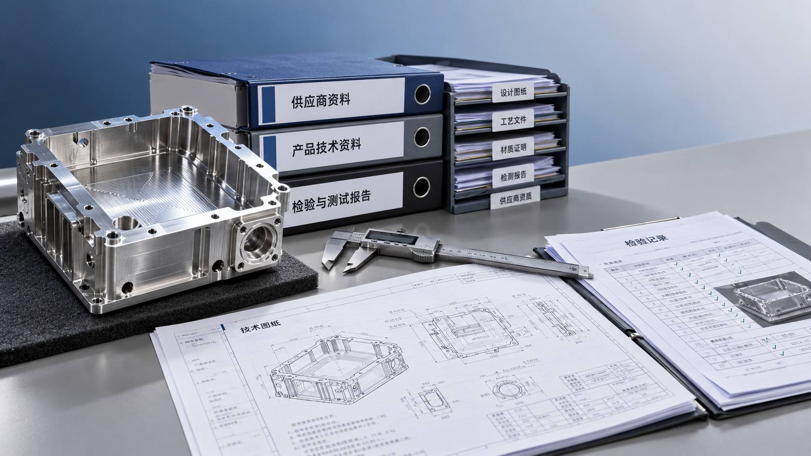
- Maintain traceability. Link images and results to the part, location, inspection procedure, equipment configuration, software version, time, and reviewer decision as required by the organization’s quality system.
Acceptance thresholds deserve particular attention. Tightening a threshold may reveal more subtle indications, but it can also increase the number of benign features sent for review. The appropriate balance depends on the consequence of a miss, the reliability of subsequent inspection, and the approved criteria for the part.
Keeping the inspection trustworthy over time
A system validated on installation does not remain trustworthy automatically. Camera movement, lighting degradation, lens contamination, software updates, new material batches, and changes in part finish can all affect results. Establish checks for image quality and coverage, control configuration changes, and define when revalidation is needed. Machine-learning models require the same discipline: new training data or a revised model can change behavior and should be assessed before operational release.
Human review also needs clear boundaries. Inspectors should know which indications the system is qualified to flag, where it cannot see, and how to handle ambiguous results. If an alert is overridden, the reason should be recorded in accordance with the applicable process. This makes the record useful for investigation and improvement rather than merely proving that an image was taken.
Aerospace inspection requirements are governed by the applicable design, production, maintenance, and regulatory framework. FAA or EASA oversight and relevant standards may be involved depending on the operation and jurisdiction, but installing a vision system does not by itself establish compliance or authorization to change an inspection task. Any substitution or modification must follow the applicable approved procedures and organizational controls.
Used within those boundaries, machine vision systems give quality and safety teams a more consistent way to examine and document visible composite features. Their greatest value comes from a well-defined inspection target, evidence of performance on representative parts, and a clear route from an image indication to the next engineering decision.
Article Categories
Latest Whitepapers
- 00
0000-00
US Space Force Predicts Swift Telescope's Uncontrolled Reentry After Rescue FailsPosted by: Dr. Julian Void - 00
0000-00
How machine vision systems detect defects in composite airframesPosted by: Dr. Aris Aero - 00
0000-00
AIA Releases 2027 Aerospace and Defense Trade PrioritiesPosted by: Dr. Aris Aero
SYSTEM_ALERT_URGENT
Q3 SYMPOSIUM ON ORBITAL DYNAMICS
Registration for the Orbital Aerospace technical committee is now open. Node access required.
Taglist:
Recent Articles
![]() Nov 01, 2026US Space Force Predicts Swift Telescope's Uncontrolled Reentry After Rescue FailsUS Space Force Predicts Swift Telescope's Uncontrolled Reentry After Rescue Fails
 Nov 01, 2026How machine vision systems detect defects in composite airframesHow machine vision systems detect defects in composite airframes
![]() Oct 31, 2026AIA Releases 2027 Aerospace and Defense Trade PrioritiesAIA Releases 2027 Aerospace and Defense Trade Priorities
 Oct 31, 2026How to assess a rail safety standards consultant’s project experienceHow to assess a rail safety standards consultant’s project experience
![]() Oct 30, 2026FCC Proposes Updated Direct-to-Device Rules and Nearly 500 MHz of SpectrumFCC Proposes Updated Direct-to-Device Rules and Nearly 500 MHz of Spectrum
 Oct 30, 2026How does DO-178C support safety certification for avionics?How does DO-178C support safety certification for avionics?
![]() Oct 29, 2026Spain High-Speed Train Collision Kills at Least 68, Prompting Safety ReviewSpain High-Speed Train Collision Kills at Least 68, Prompting Safety Review
 Oct 29, 2026Which EN 15227 crash scenarios apply to high-speed rolling stock?Which EN 15227 crash scenarios apply to high-speed rolling stock?
![]() Oct 28, 2026GE Aerospace Releases Footage of World’s First High-Altitude Hybrid-Electric Flight TestGE Aerospace Releases Footage of World’s First High-Altitude Hybrid-Electric Flight Test
 Oct 28, 2026Is Global Aerospace & Advanced Transportation-Intelligence reliable for supplier research?Is Global Aerospace & Advanced Transportation-Intelligence reliable for supplier research?
![]() Oct 27, 2026FAA Certifies Boeing 737 MAX 10 After Years of DelaysFAA Certifies Boeing 737 MAX 10 After Years of Delays
 Oct 27, 2026Can an intermodal connectivity platform reduce rail handoff delays?Can an intermodal connectivity platform reduce rail handoff delays?
![]() Oct 26, 2026Chery Unveils Global Smart Mobility Strategy Targeting Robotaxis and eVTOLsChery Unveils Global Smart Mobility Strategy Targeting Robotaxis and eVTOLs
 Oct 26, 2026How to evaluate avionics for helicopters used in IFR operationsHow to evaluate avionics for helicopters used in IFR operations
![]() Oct 25, 2026Ukraine’s Defence Minister Says SpaceX Satellite Services Restored After Speed RestrictionsUkraine’s Defence Minister Says SpaceX Satellite Services Restored After Speed Restrictions
 Oct 25, 2026How satellite infrastructure for IoT affects sensor reporting delaysHow satellite infrastructure for IoT affects sensor reporting delays
![]() Oct 24, 2026China Successfully Launches Yaogan 50-03 SatelliteChina Successfully Launches Yaogan 50-03 Satellite
 Oct 24, 2026How gradients affect traction power needs in high-speed rolling stockHow gradients affect traction power needs in high-speed rolling stock
![]() Oct 23, 2026FAA Proposes Checks on Nearly 2,000 Boeing 737NGs Over Loss-of-Control RiskFAA Proposes Checks on Nearly 2,000 Boeing 737NGs Over Loss-of-Control Risk
 Oct 23, 2026How fuel choice affects specific impulse in liquid oxygen propulsionHow fuel choice affects specific impulse in liquid oxygen propulsion
![]() Oct 22, 2026QuantumScape Plans 100 MWh Solid-State Battery Line Targeting Aerospace and Other MarketsQuantumScape Plans 100 MWh Solid-State Battery Line Targeting Aerospace and Other Markets
 Oct 22, 2026How tank size limits hydrogen aircraft range on regional flightsHow tank size limits hydrogen aircraft range on regional flights
![]() Oct 21, 2026FAA Certifies Boeing 737-10, Clearing Regulatory Hurdle for DeliveriesFAA Certifies Boeing 737-10, Clearing Regulatory Hurdle for Deliveries
 Oct 21, 2026How are electric vertical takeoff aircraft certified in the US?How are electric vertical takeoff aircraft certified in the US?
![]() Oct 20, 2026Ohio Department of Transportation Releases Three-Year Advanced Air Mobility Action PlanOhio Department of Transportation Releases Three-Year Advanced Air Mobility Action Plan
 Oct 20, 2026How does magnetic flux density in tesla affect maglev lift force?How does magnetic flux density in tesla affect maglev lift force?
![]() Oct 19, 2026ZeroAvia Completes Key Ground Tests of ZA600 Hydrogen Fuel Cell PowertrainZeroAvia Completes Key Ground Tests of ZA600 Hydrogen Fuel Cell Powertrain
 Oct 19, 2026How spacecraft integration affects advanced propulsion costsHow spacecraft integration affects advanced propulsion costs
 Oct 18, 2026How chilldown prevents cavitation in cryogenic engine systemsHow chilldown prevents cavitation in cryogenic engine systems
 Oct 17, 2026How explainability affects algorithmic trust in AI flight systemsHow explainability affects algorithmic trust in AI flight systems
 Oct 16, 2026How to evaluate transportation technology for Middle East heatHow to evaluate transportation technology for Middle East heat
 Oct 15, 2026How common-cause failures defeat redundancy logic in European avionicsHow common-cause failures defeat redundancy logic in European avionics
 Oct 14, 2026How DO-160 applies to aerospace technology testing for avionicsHow DO-160 applies to aerospace technology testing for avionics
 Oct 13, 2026How fuel price volatility shapes commercial aviation cost trendsHow fuel price volatility shapes commercial aviation cost trends
 Oct 12, 2026How to qualify aerospace manufacturing components for traceabilityHow to qualify aerospace manufacturing components for traceability