How chilldown prevents cavitation in cryogenic engine systems
Lead Author
Published
Views:
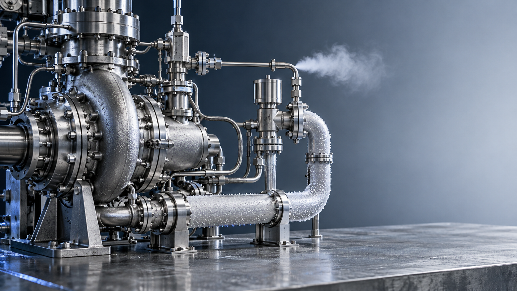
Chilldown limits cavitation by removing heat from feedlines, valves, and turbopump hardware before those components must carry the engine’s startup flow. Without sufficient cooling, incoming cryogenic propellant absorbs stored heat and partially vaporizes. The resulting vapor can disrupt pump filling while warmer liquid has less pressure margin above its saturation condition.
The important qualification is that cold hardware alone does not prove cavitation protection. Reliable startup requires liquid-dominant flow and sufficient inlet pressure throughout pump acceleration. Chilldown establishes the thermal conditions for that margin; tank pressure, feed-system losses, valve timing, and pump operating conditions determine whether the margin survives.
Thermal vapor generation and pump cavitation are connected, but different
During initial filling, liquid oxygen, liquid hydrogen, or liquid methane encounters hardware far warmer than its operating temperature. Heat transferred from the metal can boil the propellant even when the supply pressure is adequate for a fully chilled system. This is heat-driven vapor generation, not necessarily cavitation caused by a pump-induced pressure reduction.
Cavitation occurs when local liquid pressure falls sufficiently close to or below the liquid’s vapor pressure for vapor cavities to form and grow. In a turbopump, vulnerable locations include the inducer and impeller inlet, where flow acceleration and blade loading create local pressure minima. Cavities can subsequently collapse as pressure recovers.
The two mechanisms reinforce each other during startup. Vapor generated upstream enters the pump as an existing gas phase, while heat absorbed by the remaining liquid raises its vapor pressure. Both conditions weaken suction performance, but they require different diagnostic interpretations. A pump ingesting upstream vapor may lose head or experience unstable loading without every observed disturbance being attributable to locally generated cavitation.
Entrained noncondensable gas adds another distinction. Purge gas or trapped pressurant cannot be eliminated simply by cooling the liquid below its saturation temperature. A successful chilldown arrangement must therefore provide both heat removal and an effective route for displaced gas and generated vapor.
Why the first liquid does not establish a ready system
Initial liquid arrival is only the start of the thermal transient. The hardware contains stored energy that must be transferred to the propellant and carried away through vented vapor, discharged fluid, or an approved return path.
A simplified estimate of the heat to be removed from a component is:
Q ≈ mw ∫ cp,w(T) dT
Here, mw is the cooled hardware mass, and cp,w is its temperature-dependent specific heat over the relevant temperature interval. This estimate describes stored thermal energy, not total chilldown consumption. Environmental heat leak, supports, connected structures, and the enthalpy carried away by the fluid also matter.
At a sufficiently large wall-to-liquid temperature difference, a vapor film can separate the liquid from the surface. That film limits direct liquid contact and changes heat transfer. As the wall cools, transition and nucleate boiling can follow, before low-boiling or single-phase liquid flow is established. The detailed progression depends on pressure, mass flux, orientation, surface condition, and geometry; a single uniform boiling regime should not be assumed throughout the feed system.
This explains why one cold temperature reading can be misleading. A thin pipe wall may respond quickly while a thick valve body, pump casing, or poorly swept cavity retains heat. When flow is redirected during engine start, liquid can encounter those warmer surfaces and generate a fresh vapor pulse.
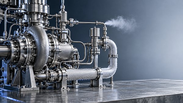
The relevant endpoint is therefore not simply a low wall temperature. It is a sufficiently cooled flow path that continues to deliver acceptable liquid conditions when valves move, flow increases, and the pump accelerates.
How chilldown improves cavitation margin
For a predominantly single-phase liquid at a defined pump-inlet reference plane, available net positive suction head can be expressed approximately as:
NPSHA = [pt,in,abs − pv(Tin)] / (ρg)
In this expression, pt,in,abs is absolute inlet total pressure, pv is vapor pressure at the inlet liquid temperature, ρ is liquid density, and g is gravitational acceleration. Pressure location and reference conventions must remain consistent with the pump data used for comparison. Static-pressure measurements require appropriate treatment of velocity head and measurement elevation.
Chilldown improves this balance mainly by limiting liquid heating and the associated rise in vapor pressure. It also reduces upstream vapor production, helping establish the liquid feed conditions under which a conventional NPSH assessment is meaningful.
It does not independently guarantee a higher inlet pressure. During chilldown or startup, increased flow, valve restrictions, two-phase pressure losses, and tank-pressure changes can offset the thermal benefit. A colder inlet can still have inadequate suction margin if its pressure falls too far.
Available NPSH must be compared with validated pump requirements at the relevant speed and flow condition. Those requirements change during acceleration. An endpoint measurement taken before rotation cannot demonstrate that the entire startup trajectory is acceptable.
There is also an important limitation in the term “required NPSH.” A value based on a specified pump-head reduction, such as NPSH3, is not a no-cavitation boundary. Cavitation inception, rotating cavitation, or unacceptable dynamic loading can occur before that head-loss criterion is reached. Rocket turbopump acceptance therefore needs the applicable stability and structural limits, not merely a positive difference between two nominal NPSH values.
Startup sequencing must preserve the conditions chilldown creates
A viable sequence provides a controlled cooling flow through the required passages, removes vapor, and establishes acceptable inlet conditions before imposing the associated pump demand. The implementation may use dedicated bypasses, vent paths, recirculation, tank-fed flow, or controlled pump operation. No single arrangement applies to every engine architecture.
The vapor outlet is part of the hydraulic design, not just a disposal connection. Excessive restriction can retain vapor or alter the cooling flow. Excessive depressurization can cause additional flashing. Vent and return conditions must therefore be evaluated together with supply pressure and the intended chilldown mass flow.
Increasing flow is not an unlimited remedy. It can shorten cooling time, but it also increases propellant consumption and pressure losses. Rapid thermal changes can impose differential contraction and thermal stress on housings, joints, seals, and clearances. The acceptable sequence must satisfy thermal and mechanical constraints as well as suction performance.
The transition into startup deserves particular attention. Opening a main valve can change the flow distribution; closing a chilldown bypass can remove a previously available vapor escape path. Pump acceleration increases suction demand, while fluid acceleration through the feedline introduces transient pressure losses. The minimum cavitation margin may occur during this transition rather than at either steady endpoint.
A hold after chilldown creates a separate exposure. Residual heat in heavy components and continuing environmental heat leak can rewarm stagnant propellant. A readiness indication should consequently have a validated hold-time basis or continuous refresh logic. Once that basis is exceeded, the system needs reassessment or a defined rechill sequence.
What measurements can actually demonstrate readiness?
Temperature, pressure, and flow need to be interpreted together. Each answers a different question, and none independently proves that the pump will receive an acceptable inlet state.
A useful thermal indicator is the local saturation-temperature margin:
ΔTsub = Tsat(plocal) − Tliquid
A positive value indicates subcooling at the measurement location. It does not prove adequate pressure at the inducer blade surface, where pressure can be lower. Nor does it exclude vapor entering from another branch. Pressure and temperature should represent the same local fluid state, with uncertainty and response time included in the assessment.
Dynamic records are essential because average values can hide short pressure minima. Pressure, temperature, valve position, shaft speed, and flow data should be time-aligned closely enough to resolve the events that set startup margin. Sampling and sensor response must be selected for the relevant transient rather than only for the overall chilldown duration.
A readiness gate should combine thermal stabilization, acceptable liquid inlet conditions, evidence of adequate gas removal, and a validated pressure margin. Exact limits and persistence times belong to the specific engine’s qualification basis; there is no universal temperature or chilldown duration that establishes cavitation protection.
Why a successful cold-flow test may not transfer directly
Cold-flow testing can establish cooling behavior, valve timing, and feed-system pressure losses. Its value depends on how well it reproduces the conditions controlling the engine transition.
Tank pressure, initial hardware temperature, propellant conditioning, orientation, vent backpressure, and pump acceleration all affect the result. A test that ends with stable liquid flow but omits representative pump acceleration does not demonstrate the minimum inlet margin during start.
Substitute fluids require particular care. Liquid-nitrogen testing can support development, but nitrogen does not reproduce all the density, viscosity, saturation, latent-heat, and thermodynamic cavitation characteristics of oxygen, hydrogen, or methane. Similar cooldown traces alone cannot establish equivalent turbopump suction performance.
Cryogenic cavitation itself also involves thermal effects: vaporization can cool the liquid near a cavity, changing local vapor pressure and cavity growth. This makes direct transfer from room-temperature water data unreliable without an appropriate correlation or validated model. The effect must not be treated as a general safety allowance that compensates for an inadequately chilled inlet.
Restart assessment adds another boundary condition. Hardware may remain partly cold while trapped fluid warms or vapor accumulates in isolated volumes. A restart sequence therefore needs evidence for its own initial thermal and fluid states, rather than automatic inheritance of the first-start chilldown limits.
The acceptance criterion is a demonstrated startup envelope
General cryogenic safety and pressure-system requirements do not supply an engine-specific cavitation margin. The governing evidence must connect thermal conditioning to pump performance: a validated thermal-hydraulic model, measured chilldown behavior, applicable pump suction and stability data, and representative startup tests.
The strongest acceptance basis identifies the limiting conditions and includes uncertainty in temperature, pressure, flow, and timing. It also defines responses to incomplete chilldown, interrupted flow, excessive hold time, and abnormal pressure behavior. A fixed timer can serve as an operational control only where testing has shown that it reliably bounds those conditions.
Chilldown prevents a major source of startup cavitation risk by removing stored heat before it can vaporize the incoming propellant. Its success is demonstrated when the conditioned system maintains acceptable liquid supply and pump stability through the actual startup transient—not when a cold sensor or an elapsed timer merely declares the hardware ready.
Article Categories
SYSTEM_ALERT_URGENT
Q3 SYMPOSIUM ON ORBITAL DYNAMICS
Registration for the Orbital Aerospace technical committee is now open. Node access required.
Taglist:
Recent Articles
![]() Oct 27, 2026FAA Certifies Boeing 737 MAX 10 After Years of DelaysFAA Certifies Boeing 737 MAX 10 After Years of Delays
 Oct 27, 2026Can an intermodal connectivity platform reduce rail handoff delays?Can an intermodal connectivity platform reduce rail handoff delays?
![]() Oct 26, 2026Chery Unveils Global Smart Mobility Strategy Targeting Robotaxis and eVTOLsChery Unveils Global Smart Mobility Strategy Targeting Robotaxis and eVTOLs
 Oct 26, 2026How to evaluate avionics for helicopters used in IFR operationsHow to evaluate avionics for helicopters used in IFR operations
![]() Oct 25, 2026Ukraine’s Defence Minister Says SpaceX Satellite Services Restored After Speed RestrictionsUkraine’s Defence Minister Says SpaceX Satellite Services Restored After Speed Restrictions
 Oct 25, 2026How satellite infrastructure for IoT affects sensor reporting delaysHow satellite infrastructure for IoT affects sensor reporting delays
![]() Oct 24, 2026China Successfully Launches Yaogan 50-03 SatelliteChina Successfully Launches Yaogan 50-03 Satellite
 Oct 24, 2026How gradients affect traction power needs in high-speed rolling stockHow gradients affect traction power needs in high-speed rolling stock
![]() Oct 23, 2026FAA Proposes Checks on Nearly 2,000 Boeing 737NGs Over Loss-of-Control RiskFAA Proposes Checks on Nearly 2,000 Boeing 737NGs Over Loss-of-Control Risk
 Oct 23, 2026How fuel choice affects specific impulse in liquid oxygen propulsionHow fuel choice affects specific impulse in liquid oxygen propulsion
![]() Oct 22, 2026QuantumScape Plans 100 MWh Solid-State Battery Line Targeting Aerospace and Other MarketsQuantumScape Plans 100 MWh Solid-State Battery Line Targeting Aerospace and Other Markets
 Oct 22, 2026How tank size limits hydrogen aircraft range on regional flightsHow tank size limits hydrogen aircraft range on regional flights
![]() Oct 21, 2026FAA Certifies Boeing 737-10, Clearing Regulatory Hurdle for DeliveriesFAA Certifies Boeing 737-10, Clearing Regulatory Hurdle for Deliveries
 Oct 21, 2026How are electric vertical takeoff aircraft certified in the US?How are electric vertical takeoff aircraft certified in the US?
![]() Oct 20, 2026Ohio Department of Transportation Releases Three-Year Advanced Air Mobility Action PlanOhio Department of Transportation Releases Three-Year Advanced Air Mobility Action Plan
 Oct 20, 2026How does magnetic flux density in tesla affect maglev lift force?How does magnetic flux density in tesla affect maglev lift force?
![]() Oct 19, 2026ZeroAvia Completes Key Ground Tests of ZA600 Hydrogen Fuel Cell PowertrainZeroAvia Completes Key Ground Tests of ZA600 Hydrogen Fuel Cell Powertrain
 Oct 19, 2026How spacecraft integration affects advanced propulsion costsHow spacecraft integration affects advanced propulsion costs
 Oct 18, 2026How chilldown prevents cavitation in cryogenic engine systemsHow chilldown prevents cavitation in cryogenic engine systems
 Oct 17, 2026How explainability affects algorithmic trust in AI flight systemsHow explainability affects algorithmic trust in AI flight systems
 Oct 16, 2026How to evaluate transportation technology for Middle East heatHow to evaluate transportation technology for Middle East heat
 Oct 15, 2026How common-cause failures defeat redundancy logic in European avionicsHow common-cause failures defeat redundancy logic in European avionics
 Oct 14, 2026How DO-160 applies to aerospace technology testing for avionicsHow DO-160 applies to aerospace technology testing for avionics
 Oct 13, 2026How fuel price volatility shapes commercial aviation cost trendsHow fuel price volatility shapes commercial aviation cost trends
 Oct 12, 2026How to qualify aerospace manufacturing components for traceabilityHow to qualify aerospace manufacturing components for traceability
 Oct 11, 2026Which certification hurdles are slowing hydrogen aviation in Europe?Which certification hurdles are slowing hydrogen aviation in Europe?
 Oct 10, 2026What evidence should a magnetic gap stability supplier provide?What evidence should a magnetic gap stability supplier provide?
 Oct 09, 2026Which ISO standards matter when qualifying industrial technology suppliers?Which ISO standards matter when qualifying industrial technology suppliers?
 Oct 08, 2026When does reusability actually lower launch vehicle costs?When does reusability actually lower launch vehicle costs?
 Oct 07, 2026Where to find reliable product knowledge resources in the Middle EastWhere to find reliable product knowledge resources in the Middle East
 Oct 06, 2026What drives high-speed rail systems cost per kilometer?What drives high-speed rail systems cost per kilometer?
 Oct 05, 2026When does hydrogen propulsion for UAV extend mission range enough to justify it?When does hydrogen propulsion for UAV extend mission range enough to justify it?
 Oct 04, 2026How rail systems integration reduces commissioning delaysHow rail systems integration reduces commissioning delays
 Oct 03, 2026How to evaluate an advanced propulsion manufacturer for hydrogen systemsHow to evaluate an advanced propulsion manufacturer for hydrogen systems
 Oct 02, 2026How to qualify aircraft components for OEM production approvalHow to qualify aircraft components for OEM production approval