How to reduce springback when bending automotive sheet metal
Lead Author
Published
Views:
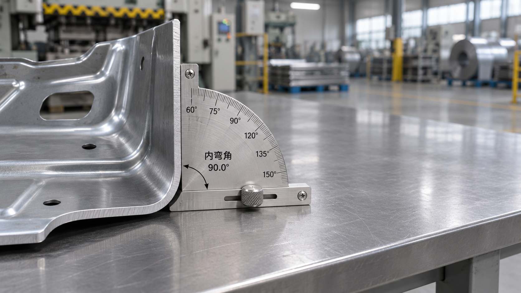
Reduce springback by measuring the bend after the sheet has been released, then adjusting the forming process to produce the required free-state shape. A controlled amount of overbending is often the first correction, but a stable result also depends on material consistency, bend direction, tooling condition, and repeatable press settings.
In sheet metal bending for automotive parts, an angle that looks correct under load can open after the tool retracts. High-strength steels are particularly sensitive because a greater elastic recovery can remain after forming. Before changing the program, determine whether the error is a consistent offset, variation between parts, or distortion across the whole component. Each points to a different correction.
Measure the released part before adjusting the press
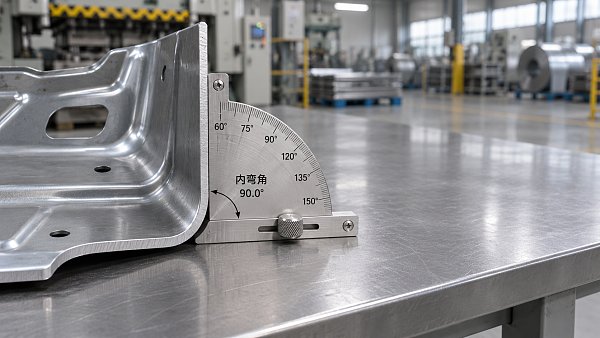
Use the drawing’s angle convention and inspection method when comparing a bend with its target. A 90-degree internal angle that opens to 93 degrees needs a different machine correction from an angle reported as a 3-degree deviation from a 90-degree bend line. Confirm whether the machine displays the included angle or the amount of bend; their numerical directions can be opposite.
Remove the part from the tooling and allow it to rest in its specified inspection condition. Measure at consistent locations with a suitable angle gauge, template, fixture, or measuring system. Long bends deserve readings near both ends and at the center: one value can conceal a twist, a bowed bend line, or uneven forming along the length.
For a simple trial, suppose the required released internal angle is 90 degrees and the first piece measures 93 degrees. The bend has opened by 3 degrees relative to the target. Apply an initial correction in the direction of more bending, then make and measure another piece. The machine setting should not automatically be changed by exactly 3 degrees, because control conventions and the relationship between programmed depth and final angle vary. Record the actual setting and result to establish the correction for that setup.
Mark the same face and bend end on each trial part. Flipping a part or measuring against a different datum can make a consistent bend look variable. Where a flange is short, use a measurement method that contacts a sufficiently flat area rather than the curved bend zone.
Separate angle error from shape error
A uniform angle that is consistently too open is a good candidate for overbend compensation. If the angle varies along the bend, changing the global bend setting may bring one location into tolerance while pushing another out.
- Ends differ from the center: investigate ram and bed deflection, crowning, tool seating, and loading across the machine. Uneven contact or worn tooling can produce a similar pattern.
- One end differs from the other: examine part alignment, backgauge contact, tool alignment, and possible twist in the blank.
- Angles pass locally, but the assembly does not fit: inspect flange length, hole position, bend-line position, and overall profile. Angular recovery can shift edges and features even when a local angle is acceptable.
- Results drift between otherwise similar pieces: review material lot, thickness, grain direction, setup changes, and measurement repeatability before making repeated program edits.
Keep measurement pressure low enough that the gauge or fixture does not force a flexible panel into shape. If the part is evaluated in a constrained fixture, distinguish the specified restrained condition from the free-state shape. A part that fits only when pushed hard into position may transfer unwanted stress into the assembly.
Use overbending as a controlled adjustment
Overbending forms the sheet beyond the desired final angle so elastic recovery brings it back toward the target. It is most effective when the material and setup produce a repeatable error. Start with a trial blank from the intended material and use the production tooling, bend orientation, and support conditions. Adjust in small increments, recording both the programmed setting and the released measurement.
Do not use one correction value for every bend in a component. Bend length, flange geometry, tool access, and local stiffness can change the result. A narrow flange next to a cutout may recover differently from a wide, uninterrupted flange, even when both use the same nominal angle.
On a press brake, penetration depth affects the formed angle, but its effect is not necessarily linear across the entire adjustment range. An aggressive depth change can create an overbent part, damage a coated surface, or exceed the permitted force for the tooling. Keep adjustments within the machine and tool limits, and use the control’s approved method for angle correction.
If several trial pieces fluctuate around the target, adding more compensation is unlikely to solve the underlying problem. First establish whether the gauge, blank positioning, material, or machine setup is contributing to the spread. A correction can move the average; it does not automatically reduce variation.
Match the tooling to the material and bend
Tool geometry changes both the forming load and the amount of recovery. In air bending, the sheet contacts the punch and die at limited locations, and the final angle depends on penetration as well as material and tooling. The resulting inside radius is influenced by the die opening and material behavior; it should not be assumed to equal the punch tip radius.
A larger inside bend radius relative to sheet thickness generally leaves more elastic recovery than a tighter bend. Reducing the radius is not a free correction: high-strength material can crack when bent too tightly, particularly at a sheared edge or in an unfavorable direction relative to rolling. Follow the approved part and material requirements, and inspect the outside surface and edges of trial bends for damage. Do not change a specified radius solely to improve the angle.
Die opening also affects the result. A wider opening can reduce forming force for a given setup, but it changes the bend geometry and can increase sensitivity to material variation. A narrower opening increases the required force and may create marking or exceed tooling limits. Select punch and die combinations against the material thickness, grade, flange length, required radius, and rated capacity; then validate the resulting part.
Bottoming or coining can reduce angular variation in some applications by applying greater pressure in the bend area. These methods require suitable tooling and substantially different force considerations from air bending. They are not a simple program change, and a press brake or tool rated for an air bend is not automatically suitable for coining. Confirm the process, force limits, surface requirements, and material formability before switching.
Control material direction and batch variation
Yield strength, thickness, and rolling direction all affect springback. Two sheets identified by the same nominal grade and thickness can still produce different released angles within their permitted material ranges. Higher strength generally increases recovery under otherwise comparable conditions, while changes in thickness alter the forming response and, in air bending, the relationship between penetration and angle.
Keep the bend orientation relative to rolling direction consistent during trials and production. Reorienting a blank to improve sheet utilization can change both springback and cracking behavior. Mark the material direction when it is not obvious on the blank, and make any nesting change part of the process review rather than treating it as a purely dimensional change.
When a new coil or lot is introduced, compare an initial part with the established reference before running a large quantity. If correction is needed, document the lot and the change. Frequent unexplained corrections within a single lot call for a closer look at thickness measurements, blank handling, and machine repeatability rather than assuming every piece has different material properties.
Account for the whole forming sequence
Springback is not limited to a bend opening after the punch lifts. Automotive brackets and panels can also develop sidewall curl, flange movement, or twist as stresses redistribute. A local angle correction will not necessarily bring the complete part into position.
For a multi-bend component, measure critical features after the full forming sequence as well as during setup. A later bend can move a datum or alter access for the gauge. Support long or flexible blanks consistently and verify that the backgauge contacts the intended edge without trapping the part against an earlier flange. When the sequence must change to clear tooling, repeat the dimensional validation.
For stamped parts formed in matched dies, springback compensation can involve changes to die geometry, draw beads, or forming conditions. Those changes affect material flow and other features, so they need tooling and process review. Pressing harder on an existing die is not a universal fix and can damage the die or change the part elsewhere.
Recognize when the process is stable
A useful setup record links the final released dimensions to the actual production conditions: material identification and direction, thickness, tool set, bend sequence, machine correction, measurement locations, and inspection method. Include observations such as surface marking or a tendency for a long flange to twist. This makes the next setup easier to reproduce and gives a meaningful reference when the result changes.
After a correction, measure more than one part made under the same conditions. A single acceptable piece shows that the target was reached once; a short run reveals whether the process remains centered and repeatable. If the angle is acceptable but cracks, excessive marking, or assembly strain appear, stop treating the angle as the only acceptance criterion and review the forming method before continuing.
Article Categories
SYSTEM_ALERT_URGENT
Q3 SYMPOSIUM ON ORBITAL DYNAMICS
Registration for the Orbital Aerospace technical committee is now open. Node access required.
Taglist:
Recent Articles
 Nov 22, 2026How does redundancy handle component failures in rail signaling?How does redundancy handle component failures in rail signaling?
![]() Nov 21, 2026Middle Eastern Countries Oppose EU Aviation Emissions Proposal at ICAOMiddle Eastern Countries Oppose EU Aviation Emissions Proposal at ICAO
 Nov 21, 2026How are reference aircraft used in unmanned aircraft R&D?How are reference aircraft used in unmanned aircraft R&D?
![]() Nov 20, 2026Helios Horizon Completes Solid-State Battery Test Flight, Sets Three World RecordsHelios Horizon Completes Solid-State Battery Test Flight, Sets Three World Records
 Nov 20, 2026How does battery weight affect electric aircraft range?How does battery weight affect electric aircraft range?
![]() Nov 19, 2026ICEYE's €2 Billion Avio Bid Meets Italian Government ResistanceICEYE's €2 Billion Avio Bid Meets Italian Government Resistance
 Nov 19, 2026Is EN 9100 certification mandatory for aerospace suppliers in Europe?Is EN 9100 certification mandatory for aerospace suppliers in Europe?
![]() Nov 18, 2026ULA Says Vulcan Failure Began at Liftoff; 40 Amazon Satellites LostULA Says Vulcan Failure Began at Liftoff; 40 Amazon Satellites Lost
 Nov 18, 2026How to verify load ratings from an industrial rigging equipment factoryHow to verify load ratings from an industrial rigging equipment factory
![]() Nov 17, 2026Collins Aerospace Breaks Ground on Propeller MRO Facility in IndiaCollins Aerospace Breaks Ground on Propeller MRO Facility in India
 Nov 17, 2026How to use a transportation benchmarking database to compare freight costsHow to use a transportation benchmarking database to compare freight costs
![]() Nov 16, 2026Beijing Drone Rules Ban Flight, Possession and Storage Across the CityBeijing Drone Rules Ban Flight, Possession and Storage Across the City
 Nov 16, 2026How does redundancy support safe autonomous aviation?How does redundancy support safe autonomous aviation?
![]() Nov 15, 2026SpaceX Catches Orbital-Class Starship on Flight 15SpaceX Catches Orbital-Class Starship on Flight 15
 Nov 15, 2026How does system integration affect smart railway station costs?How does system integration affect smart railway station costs?
![]() Nov 14, 2026SpaceX Starship Flight 15 Reaches Orbit as Booster Diverts to SplashdownSpaceX Starship Flight 15 Reaches Orbit as Booster Diverts to Splashdown
 Nov 14, 2026How to verify a technical compliance reference for avionicsHow to verify a technical compliance reference for avionics
![]() Nov 13, 2026Hydrogen Aviation Startups Seek Near-Term Revenue in Defense and Data CentersHydrogen Aviation Startups Seek Near-Term Revenue in Defense and Data Centers
 Nov 13, 2026How to use procurement planning resources to set lead timesHow to use procurement planning resources to set lead times
![]() Nov 12, 2026Hydrogen Aviation Startups Turn to Defense and Data Centers for RevenueHydrogen Aviation Startups Turn to Defense and Data Centers for Revenue
 Nov 12, 2026How does a multimodal logistics hub warehouse connect rail and road freight?How does a multimodal logistics hub warehouse connect rail and road freight?
![]() Nov 11, 2026FAA Rolls Out SMART AI Traffic Management System Across 22 CentersFAA Rolls Out SMART AI Traffic Management System Across 22 Centers
 Nov 11, 2026How does runway traffic management prevent runway incursions?How does runway traffic management prevent runway incursions?
![]() Nov 10, 2026FAA Starts Air Traffic Control Upgrade, Phasing Out 8-Inch Floppy DisksFAA Starts Air Traffic Control Upgrade, Phasing Out 8-Inch Floppy Disks
 Nov 10, 2026How to assess data comparability in industrial technology benchmarking softwareHow to assess data comparability in industrial technology benchmarking software
![]() Nov 09, 2026Marble Imaging Raises €6 Million for German VHR Satellite ConstellationMarble Imaging Raises €6 Million for German VHR Satellite Constellation
 Nov 09, 2026How does cryogenic propulsion for upper stages affect payload capacity?How does cryogenic propulsion for upper stages affect payload capacity?
![]() Nov 08, 2026SpaceX Plans Starship Flight 15 on November 13 With Two-Stage Catch AttemptSpaceX Plans Starship Flight 15 on November 13 With Two-Stage Catch Attempt
 Nov 08, 2026How to verify an aerospace technical reference is currentHow to verify an aerospace technical reference is current
![]() Nov 07, 2026NTSB: Southwest 737 MAX Flew 44 Times After Missed Storm Check, Leading to Dutch RollNTSB: Southwest 737 MAX Flew 44 Times After Missed Storm Check, Leading to Dutch Roll
 Nov 07, 2026How to reduce springback when bending automotive sheet metalHow to reduce springback when bending automotive sheet metal
![]() Nov 06, 2026AutoFlight Completes First Autonomous Formation Flight With Five Mixed-Weight eVTOLsAutoFlight Completes First Autonomous Formation Flight With Five Mixed-Weight eVTOLs
 Nov 06, 2026How to find current avionics standards in global aerospace technical referencesHow to find current avionics standards in global aerospace technical references
 Nov 05, 2026How does aircraft certification differ across the Middle East?How does aircraft certification differ across the Middle East?
![]() Nov 04, 2026Spain’s Transport Minister Resigns After Fatal High-Speed Rail CollisionSpain’s Transport Minister Resigns After Fatal High-Speed Rail Collision