Which certification hurdles are slowing hydrogen aviation in Europe?
Lead Author
Published
Views:
Hydrogen aircraft concepts in Europe are being slowed less by a single missing rule than by the difficulty of proving that several unfamiliar hazards remain controlled throughout an aircraft’s life. A propulsion demonstrator can show that hydrogen produces usable thrust or electrical power. Certification must establish a far broader safety case: fuel containment after damage, predictable behaviour during abnormal heat loads, safe venting in flight and on the ground, electrical fault containment, maintainability, and compatibility with airport operations.
European approval pathways are therefore demanding evidence at the interfaces between established certification domains. Turbine engines, composite structures, fuel cells, high-voltage distribution, cryogenic tanks, and ground refuelling each have relevant engineering precedents. Their combination inside a transport-category or regional aircraft changes the failure conditions. The central question is whether the aircraft can tolerate credible faults without creating an uncontrolled flammable atmosphere, unacceptable structural damage, loss of essential functions, or an evacuation hazard.
Certification bases are still being tailored to the architecture
Conventional aircraft certification requirements were developed around kerosene as the dominant energy carrier. Hydrogen introduces properties that affect assumptions embedded in those requirements: low molecular size, high diffusivity, wide flammability limits, low ignition energy, very low liquid temperature, and, for liquid storage, continuous management of boil-off and pressure. Existing airworthiness principles remain relevant, but the means of compliance often require project-specific interpretation or special conditions where the design has no direct conventional analogue.
This work starts early because the selected energy architecture determines the regulatory questions. A compressed-gas system presents a different substantiation burden from a liquid-hydrogen system. Hydrogen burned in a modified turbine raises questions around fuel-system integrity, combustion stability, emissions characterization, and engine installation. Hydrogen converted through fuel cells brings pressure vessels and distribution equipment together with power electronics, motors, thermal management, and high-voltage protection. A hybrid design can inherit the difficult aspects of both paths.
Delays arise when a programme treats the certification basis as a document to finalize after design maturity. The approval framework instead shapes the layout, fault assumptions, test articles, instrumentation, and development sequence. If a tank location, vent-mast arrangement, or electrical-zone boundary changes late, earlier safety analyses may no longer represent the aircraft that will be tested.
Cryogenic containment is an airframe problem, not just a tank problem
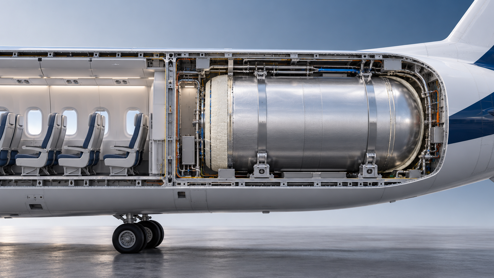
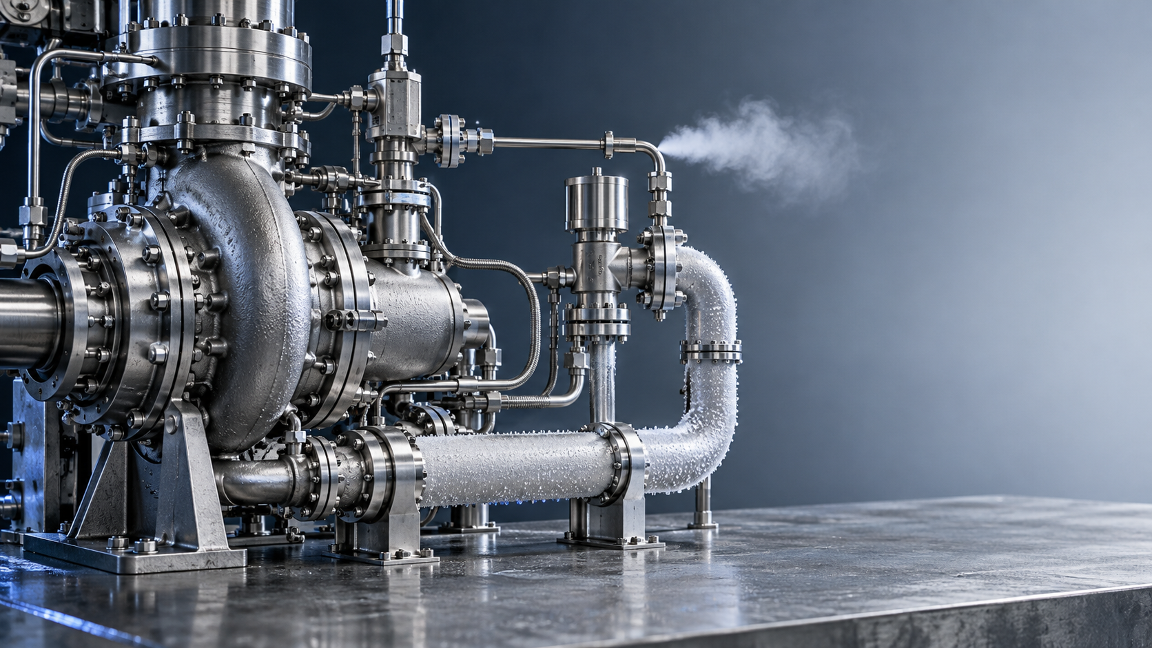
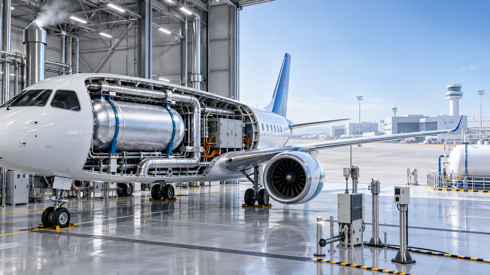
Liquid hydrogen offers a favourable energy-to-mass relationship, yet its storage temperature introduces a demanding integration case. The tank must withstand internal pressure, vibration, fatigue, crash-related loads, and thermal cycling while limiting heat ingress. Insulation performance cannot be assessed only by a steady-state heat-leak value measured on a representative vessel. Installation details matter: support straps, pipe penetrations, access panels, structural interfaces, drain paths, and local repairs can create thermal bridges or moisture traps that a laboratory configuration does not reveal.
Material selection also needs evidence beyond nominal cryogenic suitability. Metallic components can change toughness and fatigue performance at low temperature. Seals, adhesives, composite matrices, coatings, and multilayer insulation must retain function through the expected temperature range, pressure cycles, vibration spectrum, and exposure to contaminants. A test coupon may survive thermal cycling while a joined assembly develops leakage along a bonded interface, through a fitting, or at a transition between materials with different coefficients of thermal expansion.
Placement of cryogenic tanks creates airframe-level trade-offs. A location near the fuselage centreline may simplify balance management but can complicate emergency egress, pressure-vessel protection, cabin zoning, and maintenance access. An aft installation changes centre-of-gravity movement as fuel is consumed. A tank within a pressurised fuselage section introduces additional questions about leakage detection, ventilation, and the ability to isolate a fault without compromising occupied spaces.
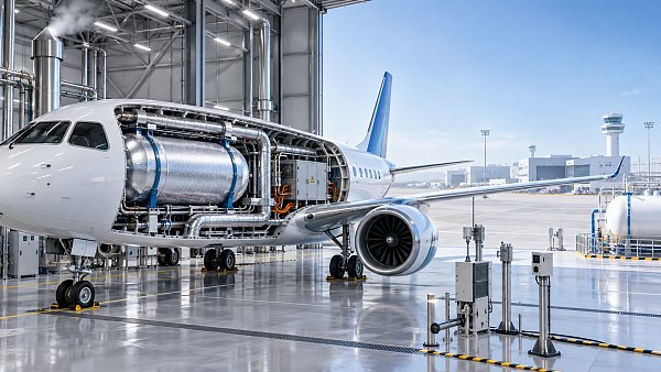
The certification evidence must connect these details. Structural substantiation, thermal analysis, leak testing, pressure-relief sizing, fire assessment, and crashworthiness cannot be submitted as independent claims when a single event affects all of them. For example, an external impact that damages insulation may change boil-off, local material temperature, tank pressure, and vent discharge conditions. The safety case needs to show how detection, isolation, relief, and crew indication respond as a system.
Leak detection and venting are difficult to validate at aircraft scale
Hydrogen does not behave like a visible liquid leak. Small releases can disperse quickly, accumulate in poorly ventilated high points, or ignite from sources that would not normally be treated as severe hazards. The useful compliance question is not merely whether a sensor detects hydrogen. It is whether the sensor arrangement detects the relevant release before concentration, location, and duration create a hazardous condition under the full range of operating states.
That requires consideration of parked aircraft, taxi, climb, cruise, descent, maintenance, refuelling, and post-shutdown conditions. Airflow paths change with ram air, pack operation, doors, vents, temperature gradients, and aircraft attitude. A sensor that performs well beside a controlled test leak may provide weak coverage when a release occurs behind insulation, inside a bay with complex geometry, or in a stagnant region above equipment. Sensor response time, cross-sensitivity, calibration drift, diagnostic coverage, and failure annunciation become part of the argument.
Venting creates a related issue. Pressure-relief devices and normal boil-off vents must discharge hydrogen away from ignition sources, intakes, occupied areas, sensitive equipment, and locations where recirculation is plausible. A geometric clearance shown on a drawing is insufficient. The discharge plume can be affected by wind, aircraft motion, local surface geometry, adjacent vehicles, and the heat state of the system. Ground and in-flight conditions need separate treatment because the surrounding flow field and potential ignition sources differ substantially.
- Normal venting needs a defined operating envelope, including cold soak, extended ground delay, and cases where fuel transfer or conditioning equipment is unavailable.
- Relief discharge must be assessed alongside nearby electrical equipment, auxiliary power operation, and the possibility of hydrogen entering enclosed volumes through drains or openings.
- A vent route that is acceptable in cruise may be unsuitable at a gate, where personnel, service vehicles, terminal structures, and neighbouring aircraft alter the hazard boundary.
Fuel-cell and high-voltage systems create coupled failure conditions
Fuel-cell propulsion is often described as an electrical aircraft configuration, but the approval challenge lies in the coupling between electrochemical, thermal, hydrogen, and electrical faults. A fuel-cell stack requires controlled reactant supply, humidity and temperature management, purge handling, and fault detection. Degradation can change operating margins gradually, while a valve, sensor, or cooling fault can create a faster transient. The system safety assessment has to distinguish between a loss of propulsion command, a controlled derate, an electrical isolation event, and a condition that also releases hydrogen.
High-voltage distribution adds electrical arcing, insulation coordination, electromagnetic compatibility, thermal runaway interactions where batteries are present, and protection-selectivity questions. Isolation devices must function under the voltage, current, temperature, vibration, and fault-current conditions that exist in the installed aircraft. A protective device validated on a bench may behave differently when cable routing, inductance, cooling, or enclosure pressure differ from the test arrangement.
Electrical segregation also affects the hydrogen safety case. A leak zone should not contain ignition-capable equipment unless protection and separation are convincingly demonstrated. Yet physical separation can be constrained by mass, aerodynamic packaging, serviceability, and redundant routing requirements. The resulting design often depends on a combination of enclosure integrity, ventilation, monitored isolation, automatic shutdown logic, and controlled venting. Each layer needs an allocated function and credible failure assumptions; simply listing several protections does not show that common-cause faults have been addressed.
Fire protection has to address hydrogen-specific scenarios
Hydrogen flames can be difficult to detect visually, and a cryogenic release may cause local cold damage before ignition. Conventional fire-zone concepts still provide a starting point, but the substantiation must cover both non-ignited and ignited releases. For an ignited leak, the issue is not only whether a detector activates. It is whether the aircraft can isolate fuel, maintain required flight capability, prevent propagation into critical structure or systems, and provide the crew with an unambiguous response.
Suppression effectiveness cannot be assumed from kerosene experience. Interrupting the flame does not remove the release source, and an extinguishing agent may be poorly suited to a jet flame or inaccessible leak location. Design attention therefore shifts toward rapid isolation, robust shutoff-valve performance, line-break protection where appropriate, venting, heat shielding, and confirmation that commands have achieved the intended state. A valve position indication alone may not prove that downstream flow has stopped.
Thermal exposure cases need careful definition. Composite airframe structure, insulation systems, wiring, and pressure vessels can react differently to local heating. The relevant test or analysis must represent installation geometry, heat flux, duration, and shielding rather than relying solely on material flammability ratings. Certification discussions often become prolonged when these assumptions are inherited from a different fuel or a different aircraft zone.
Propulsion integration extends beyond nominal thrust performance
Hydrogen combustion in a turbine requires an engine and installation case that addresses starts, relights, transient response, fuel metering, combustor behaviour, and effects on the aircraft systems that support the engine. Fuel characteristics can alter injector design, purge logic, leak paths, and the consequences of a stuck valve. Demonstrating stable operation at selected test points does not by itself establish adequate behaviour across starts at altitude, rapid throttle changes, degraded sensor inputs, or emergency shutdown sequences.
For distributed electric propulsion, loss-of-thrust analyses become more complex when power sources, converters, motors, cooling loops, and supervisory controls have shared dependencies. Redundancy claims must be traced through physical routes and common services. Two motor channels are not independent if they rely on a shared cooling manifold, common hydrogen detection logic, the same power-conversion enclosure, or adjacent wiring vulnerable to one thermal event.
Software assurance also becomes more prominent. Control software may command fuel valves, purge cycles, stack operating points, contactors, cooling hardware, and propulsors during fault recovery. The intended behaviour must be deterministic, verified, and compatible with crew alerts. Ambiguous mode transitions are particularly problematic when an automatic system has to balance propulsion continuity against hydrogen isolation.
Ground infrastructure belongs at the certification interface
Aircraft approval does not certify an entire airport, but aircraft assumptions about refuelling, parking, purging, and maintenance must be operationally credible. A liquid-hydrogen aircraft needs defined conditions for coupling and uncoupling, grounding or bonding, emergency release, spill or vent response, equipment clearances, and verification of fuel quality and temperature. Compressed hydrogen introduces its own pressure-management and connection-integrity concerns.
The boundary between aircraft design and ground procedure can create avoidable gaps. A refuelling procedure may assume an aircraft valve sequence that is not adequately protected against erroneous operation. Conversely, an aircraft design may depend on turnaround equipment able to control venting or conditioning within narrow limits. These assumptions need a controlled interface definition, including abnormal states such as incomplete transfer, connector leakage, loss of electrical power, or a vehicle movement during servicing.
Maintenance presents a quieter but persistent certification hurdle. Hydrogen sensors, insulation systems, valves, seals, and electrical isolation monitors require inspection intervals and fault-detection coverage that can be justified. Access panels and disconnects must allow servicing without introducing contamination, damaged insulation, incorrect reassembly, or trapped gas volumes. A design that is safe when newly assembled can become difficult to approve when its continued airworthiness instructions do not reliably preserve that condition.
Evidence quality determines whether the programme converges
The most productive approval packages link hazards to requirements, design features, verification methods, and configuration-controlled results. Test evidence should identify the production-representative hardware, instrumentation uncertainty, environmental conditions, failure insertion method, and acceptance criteria. Analyses need clear model assumptions and validation boundaries. A computational fluid model of vent dispersion, for instance, gains much more weight when its treatment of geometry, release rate, wind, and turbulence has been checked against relevant physical testing.
Early integrated tests are valuable because they expose interface faults that component qualification misses: condensation at a support penetration, sensor blind spots after equipment relocation, unexpected electrical noise during valve operation, or a thermal transient caused by control timing. These findings are not merely development issues. They often alter the certification argument, test matrix, and instructions for continued airworthiness.
European hydrogen aviation will move faster when the design definition and the compliance strategy mature together. The hurdle is not the absence of engineering solutions. It is demonstrating, with traceable and installation-representative evidence, that those solutions remain effective across normal operation, foreseeable faults, maintenance, and ground handling.
Article Categories
SYSTEM_ALERT_URGENT
Q3 SYMPOSIUM ON ORBITAL DYNAMICS
Registration for the Orbital Aerospace technical committee is now open. Node access required.
Recent Articles
![]() Oct 27, 2026FAA Certifies Boeing 737 MAX 10 After Years of DelaysFAA Certifies Boeing 737 MAX 10 After Years of Delays
 Oct 27, 2026Can an intermodal connectivity platform reduce rail handoff delays?Can an intermodal connectivity platform reduce rail handoff delays?
![]() Oct 26, 2026Chery Unveils Global Smart Mobility Strategy Targeting Robotaxis and eVTOLsChery Unveils Global Smart Mobility Strategy Targeting Robotaxis and eVTOLs
 Oct 26, 2026How to evaluate avionics for helicopters used in IFR operationsHow to evaluate avionics for helicopters used in IFR operations
![]() Oct 25, 2026Ukraine’s Defence Minister Says SpaceX Satellite Services Restored After Speed RestrictionsUkraine’s Defence Minister Says SpaceX Satellite Services Restored After Speed Restrictions
 Oct 25, 2026How satellite infrastructure for IoT affects sensor reporting delaysHow satellite infrastructure for IoT affects sensor reporting delays
![]() Oct 24, 2026China Successfully Launches Yaogan 50-03 SatelliteChina Successfully Launches Yaogan 50-03 Satellite
 Oct 24, 2026How gradients affect traction power needs in high-speed rolling stockHow gradients affect traction power needs in high-speed rolling stock
![]() Oct 23, 2026FAA Proposes Checks on Nearly 2,000 Boeing 737NGs Over Loss-of-Control RiskFAA Proposes Checks on Nearly 2,000 Boeing 737NGs Over Loss-of-Control Risk
 Oct 23, 2026How fuel choice affects specific impulse in liquid oxygen propulsionHow fuel choice affects specific impulse in liquid oxygen propulsion
![]() Oct 22, 2026QuantumScape Plans 100 MWh Solid-State Battery Line Targeting Aerospace and Other MarketsQuantumScape Plans 100 MWh Solid-State Battery Line Targeting Aerospace and Other Markets
 Oct 22, 2026How tank size limits hydrogen aircraft range on regional flightsHow tank size limits hydrogen aircraft range on regional flights
![]() Oct 21, 2026FAA Certifies Boeing 737-10, Clearing Regulatory Hurdle for DeliveriesFAA Certifies Boeing 737-10, Clearing Regulatory Hurdle for Deliveries
 Oct 21, 2026How are electric vertical takeoff aircraft certified in the US?How are electric vertical takeoff aircraft certified in the US?
![]() Oct 20, 2026Ohio Department of Transportation Releases Three-Year Advanced Air Mobility Action PlanOhio Department of Transportation Releases Three-Year Advanced Air Mobility Action Plan
 Oct 20, 2026How does magnetic flux density in tesla affect maglev lift force?How does magnetic flux density in tesla affect maglev lift force?
![]() Oct 19, 2026ZeroAvia Completes Key Ground Tests of ZA600 Hydrogen Fuel Cell PowertrainZeroAvia Completes Key Ground Tests of ZA600 Hydrogen Fuel Cell Powertrain
 Oct 19, 2026How spacecraft integration affects advanced propulsion costsHow spacecraft integration affects advanced propulsion costs
 Oct 18, 2026How chilldown prevents cavitation in cryogenic engine systemsHow chilldown prevents cavitation in cryogenic engine systems
 Oct 17, 2026How explainability affects algorithmic trust in AI flight systemsHow explainability affects algorithmic trust in AI flight systems
 Oct 16, 2026How to evaluate transportation technology for Middle East heatHow to evaluate transportation technology for Middle East heat
 Oct 15, 2026How common-cause failures defeat redundancy logic in European avionicsHow common-cause failures defeat redundancy logic in European avionics
 Oct 14, 2026How DO-160 applies to aerospace technology testing for avionicsHow DO-160 applies to aerospace technology testing for avionics
 Oct 13, 2026How fuel price volatility shapes commercial aviation cost trendsHow fuel price volatility shapes commercial aviation cost trends
 Oct 12, 2026How to qualify aerospace manufacturing components for traceabilityHow to qualify aerospace manufacturing components for traceability
 Oct 11, 2026Which certification hurdles are slowing hydrogen aviation in Europe?Which certification hurdles are slowing hydrogen aviation in Europe?
 Oct 10, 2026What evidence should a magnetic gap stability supplier provide?What evidence should a magnetic gap stability supplier provide?
 Oct 09, 2026Which ISO standards matter when qualifying industrial technology suppliers?Which ISO standards matter when qualifying industrial technology suppliers?
 Oct 08, 2026When does reusability actually lower launch vehicle costs?When does reusability actually lower launch vehicle costs?
 Oct 07, 2026Where to find reliable product knowledge resources in the Middle EastWhere to find reliable product knowledge resources in the Middle East
 Oct 06, 2026What drives high-speed rail systems cost per kilometer?What drives high-speed rail systems cost per kilometer?
 Oct 05, 2026When does hydrogen propulsion for UAV extend mission range enough to justify it?When does hydrogen propulsion for UAV extend mission range enough to justify it?
 Oct 04, 2026How rail systems integration reduces commissioning delaysHow rail systems integration reduces commissioning delays
 Oct 03, 2026How to evaluate an advanced propulsion manufacturer for hydrogen systemsHow to evaluate an advanced propulsion manufacturer for hydrogen systems
 Oct 02, 2026How to qualify aircraft components for OEM production approvalHow to qualify aircraft components for OEM production approval