Grid Harmonics Stability Mitigation: Methods That Reduce Resonance Risk
Lead Author
Published
Views:
Why Grid Harmonics Stability Mitigation Matters Earlier Than Many Programs Expect

Grid harmonics stability mitigation becomes critical when electrified mobility platforms move from isolated components to tightly coupled power ecosystems.
In aerospace, rail, and extreme-environment logistics, resonance rarely starts as a single equipment problem.
It usually appears when converters, storage systems, switching loads, and protection schemes interact across different frequencies.
That is why grid harmonics stability mitigation is not only about cleaner waveforms.
It is about preserving control stability, avoiding nuisance trips, limiting thermal stress, and protecting certification margins.
Within the G-AIT context, the issue is especially relevant because future mobility systems combine aggressive power density with strict safety frameworks.
A sub-orbital support facility, a 600 km/h maglev corridor, and an eVTOL charging network may all face harmonics.
Their mitigation priorities, however, are not the same.
The practical question is not whether harmonics exist.
The practical question is which resonance paths matter in each operating scene, and which methods reduce risk without adding new constraints.
Different Mobility Systems Create Different Resonance Conditions
In actual deployment, demand differences come from network stiffness, switching behavior, grounding architecture, and load volatility.
Aviation-adjacent power systems often operate with weight, redundancy, and thermal limits that narrow the mitigation window.
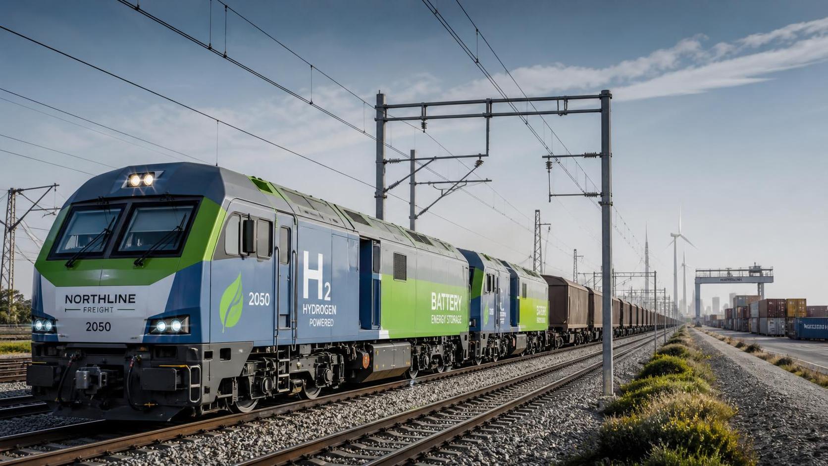
Rail systems care more about feeder length, regenerative braking interaction, and signaling immunity.
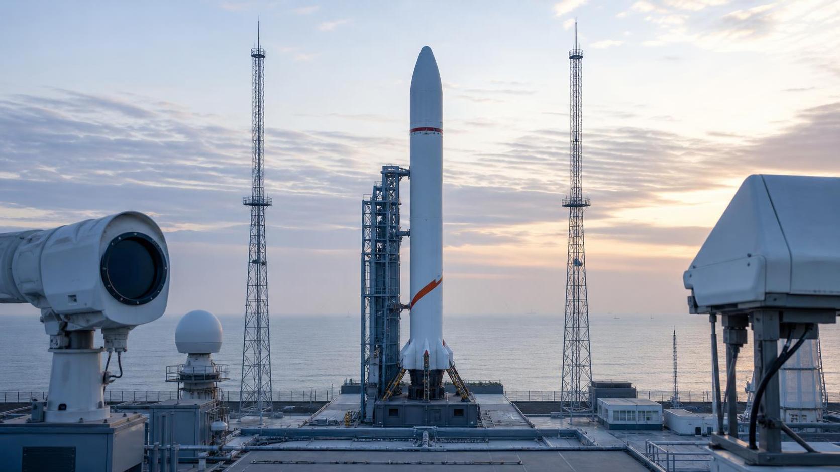
Space and remote logistics sites usually face weak grids, islanded microgrids, or rapid step changes in mission loads.
Urban air mobility introduces another pattern.
Fast charging, distributed power electronics, and grid interface equipment can create harmonic amplification during peak utilization windows.
So grid harmonics stability mitigation has to be judged against operating context, not just against a lab-side harmonic limit.
More often, the right starting point is to map harmonic sources, impedance shifts, and control interactions across expected mission states.
What usually changes the mitigation choice
- Short-circuit ratio and overall grid stiffness
- Number and type of active converters operating simultaneously
- Presence of regenerative loads or bidirectional power flow
- Sensitivity of nearby control, avionics, signaling, or communication systems
- Applicable compliance frameworks such as FAA, EASA, UIC, and ISO-linked design constraints
Where Aerospace Platforms Need Tighter Harmonic Judgement
For next-generation airframes and zero-emission propulsion test environments, harmonic problems often hide inside integrated electrical architectures.
The concern is not simply total harmonic distortion.
Control-loop interaction between inverters, motor drives, energy storage, and ground support interfaces can trigger unstable oscillations.
In this setting, grid harmonics stability mitigation usually favors coordinated control tuning, passive filter verification, and impedance-based modeling.
Adding a filter without checking mode shifts can move resonance into a more damaging frequency range.
Another common oversight appears during certification-oriented testing.
Systems may look stable at nominal loads, then behave differently during transient recharge, propulsion ramp-up, or emergency power transfer.
A more reliable approach is to test grid harmonics stability mitigation against worst-case operational sequences, not average duty points.
Rail and Maglev Networks Usually Shift the Focus to Network Interaction
High-speed rail and maglev systems present a broader electrical geography.
Resonance risk may build across substations, feeders, traction converters, station loads, and regenerative braking patterns.
Here, grid harmonics stability mitigation often has to protect both power quality and signaling reliability.
That dual requirement changes the evaluation method.
A mitigation measure that lowers one harmonic band can still be unsuitable if it increases electromagnetic interference near trackside systems.
More common in rail projects is the need to compare several operating states.
Empty-load operation, dense timetable operation, and regenerative peaks can produce different impedance signatures.
That is why network-level studies, tuned filters, and substation coordination usually outperform isolated equipment fixes.
Charging Hubs and Distributed Power Nodes Need Dynamic Mitigation
Urban air mobility and autonomous transport hubs create a different pattern from legacy infrastructure.
The issue is less about one large disturbance and more about synchronized smaller events.
Fast chargers, battery buffers, HVAC loads, and digital control systems can interact in ways that vary hour by hour.
In these cases, grid harmonics stability mitigation benefits from active filtering, harmonic monitoring, and charging sequence management.
A fixed mitigation setting may look adequate during commissioning, then underperform once utilization density rises.
A useful judgement point is whether the site will face repeated coincident switching events.
If yes, static assumptions are rarely enough.
Grid harmonics stability mitigation should then include operating envelopes, control priorities, and periodic revalidation.
Remote, Space, and Extreme-Environment Sites Often Expose Hidden Weak-Grid Problems
Mission-critical sites are often evaluated too narrowly.
Design teams may check harmonic compliance at the point of common coupling, yet miss control interaction inside the site microgrid.
That mistake becomes costly where cryogenic systems, launch support loads, autonomous logistics equipment, or shelter life-support systems share limited generation.
For these environments, grid harmonics stability mitigation usually depends on sequencing and source diversity as much as on filtering hardware.
Generator sets, storage converters, and renewable inverters can form unstable combinations under low-inertia conditions.
A practical recommendation is to evaluate black-start, islanding, and degraded-mode operation separately.
The resonance profile during contingency operation is often very different from the normal profile.
Conditions that are easy to underestimate
- Cable length changes after layout revisions
- Software updates that alter converter switching behavior
- Seasonal thermal effects on filter performance
- Temporary operating modes during maintenance or fault isolation
- Expansion phases that add new nonlinear loads later
Where Grid Harmonics Stability Mitigation Is Commonly Misjudged
One frequent misjudgment is treating harmonic compliance and stability as the same issue.
A site can meet distortion limits and still experience resonance, oscillation, or control malfunction.
Another mistake is selecting mitigation hardware from nameplate ratings alone.
Without impedance data and operating-state analysis, that choice can shift the problem instead of reducing it.
Similar applications are also often treated as identical.
An airport charging yard, a rail depot, and a spaceport utility node may use comparable converters.
Their grounding, redundancy, and fault response expectations are still very different.
The more dependable method is to connect grid harmonics stability mitigation to system architecture, maintenance reality, and compliance exposure.
A Practical Path to Match Mitigation Methods With Real Operating Conditions
In practice, the best results come from a staged evaluation rather than a single technology decision.
Start by identifying harmonic sources, vulnerable frequencies, and mission states with the highest instability consequence.
Then compare whether passive filters, active filters, control retuning, network reconfiguration, or energy buffering address the real trigger.
For G-AIT-aligned infrastructure, benchmark the mitigation path against both performance targets and certification-related constraints.
That keeps grid harmonics stability mitigation tied to operational integrity rather than to a narrow component view.
Before implementation, it is worth formalizing a short decision set.
- Map operating modes, including degraded and transient conditions
- Confirm impedance characteristics across expected expansion stages
- Check interaction with protection, signaling, avionics, and digital controls
- Estimate maintenance burden and retuning frequency
- Validate that mitigation remains effective after software and load changes
That sequence gives a stronger basis for comparing options, defining test plans, and reducing resonance risk before it reaches operations.
Article Categories
Latest Whitepapers
- 00
0000-00
What GoA4 autonomous rail requires for safe unattended operationPosted by: Marcus Track - 00
0000-00
What drives orbital data analytics pricing for satellite operators?Posted by: Dr. Julian Void - 00
0000-00
How cross-border standards shape high-speed rail infrastructure in EuropePosted by: Marcus Track
SYSTEM_ALERT_URGENT
Q3 SYMPOSIUM ON ORBITAL DYNAMICS
Registration for the Orbital Aerospace technical committee is now open. Node access required.
Recent Articles
 Sep 12, 2026What GoA4 autonomous rail requires for safe unattended operationWhat GoA4 autonomous rail requires for safe unattended operation
 Sep 11, 2026What drives orbital data analytics pricing for satellite operators?What drives orbital data analytics pricing for satellite operators?
 Sep 10, 2026How cross-border standards shape high-speed rail infrastructure in EuropeHow cross-border standards shape high-speed rail infrastructure in Europe
 Sep 09, 2026How propulsion physics shapes an aircraft’s fuel efficiencyHow propulsion physics shapes an aircraft’s fuel efficiency
 Sep 08, 2026When does a railway digital twin platform justify its cost?When does a railway digital twin platform justify its cost?
 Sep 07, 2026How fail operational systems maintain aircraft control after a faultHow fail operational systems maintain aircraft control after a fault
 Sep 07, 2026How to evaluate a power electronics price quote for avionics systemsHow to evaluate a power electronics price quote for avionics systems
 Sep 05, 2026What evidence is needed to support aircraft certification?What evidence is needed to support aircraft certification?
 Sep 04, 2026Do cryogenic propulsion systems suit satellite infrastructure?Do cryogenic propulsion systems suit satellite infrastructure?
 Sep 03, 2026When should an Urban Air Mobility OEM pursue FAA type certification?When should an Urban Air Mobility OEM pursue FAA type certification?
 Sep 02, 2026How aerospace manufacturing in Europe is adapting to supply chain riskHow aerospace manufacturing in Europe is adapting to supply chain risk
 Sep 01, 2026When does a B2B product knowledge base reduce sales support delays?When does a B2B product knowledge base reduce sales support delays?
 Aug 31, 2026Can zero emission flight in the Middle East withstand extreme heat?Can zero emission flight in the Middle East withstand extreme heat?
 Aug 30, 2026When does an aerospace conglomerate strategy reduce program risk?When does an aerospace conglomerate strategy reduce program risk?
 Aug 29, 2026How to assess a high-speed rail supplier's signaling reliabilityHow to assess a high-speed rail supplier's signaling reliability
 Aug 28, 2026How to assess the safety case for an autonomous flight system for cargoHow to assess the safety case for an autonomous flight system for cargo
 Aug 27, 2026How thermal control prevents equipment overheating on the lunar surfaceHow thermal control prevents equipment overheating on the lunar surface
 Aug 26, 2026How to evaluate an aerospace R&D reference in Southeast AsiaHow to evaluate an aerospace R&D reference in Southeast Asia
 Aug 25, 2026When train control systems integration fails, where do delays usually start?When train control systems integration fails, where do delays usually start?
 Aug 24, 2026What sets an Urban Air Mobility OEM apart in certification readinessWhat sets an Urban Air Mobility OEM apart in certification readiness
 Aug 23, 2026What makes an aerospace intelligence provider reliable for fleet risk monitoringWhat makes an aerospace intelligence provider reliable for fleet risk monitoring
 Aug 22, 2026How to verify surgicalinstruments meet sterilization standardsHow to verify surgicalinstruments meet sterilization standards
 Aug 21, 2026What to compare when evaluating autonomous rail systems vendorsWhat to compare when evaluating autonomous rail systems vendors
 Aug 20, 2026Do GaN chargers run too hot when charging laptops at full power?Do GaN chargers run too hot when charging laptops at full power?
 Aug 19, 2026What is slowing the decarbonization of rail in North AmericaWhat is slowing the decarbonization of rail in North America
 Aug 18, 2026When does intermodal connectivity for ports become a bottleneckWhen does intermodal connectivity for ports become a bottleneck
 Aug 17, 2026When can clean hydrogen aircraft compete with SAF on operating cost?When can clean hydrogen aircraft compete with SAF on operating cost?
 Aug 16, 2026China Tightens Case-by-Case Review of Drone Exports to the U.S.China Tightens Case-by-Case Review of Drone Exports to the U.S.
 Aug 16, 2026What drives low vacuum tube transport energy consumption per kilometerWhat drives low vacuum tube transport energy consumption per kilometer
 Aug 15, 2026China Expands Cross-Border Cash Pooling Nationwide for MultinationalsChina Expands Cross-Border Cash Pooling Nationwide for Multinationals
 Aug 15, 2026Are solar panels wholesale Europe prices lower for large orders?Are solar panels wholesale Europe prices lower for large orders?
 Aug 14, 2026China Imposes Temporary Export Ban on Helium, Squeezing Cryogenic and Medical Supply ChainsChina Imposes Temporary Export Ban on Helium, Squeezing Cryogenic and Medical Supply Chains
 Aug 14, 2026UIC Safety Standards Guide: What to Check Before Certifying Rail SystemsUIC Safety Standards Guide: What to Check Before Certifying Rail Systems
 Aug 13, 2026The 12th launch of Jielong-3 drives remote sensing cooperation and re-evaluation of procurement optionsThe 12th launch of Jielong-3 drives remote sensing cooperation and re-evaluation of procurement options
 Aug 13, 2026Railway signaling procurement guide: key specs and compliance checks before buyingRailway signaling procurement guide: key specs and compliance checks before buying